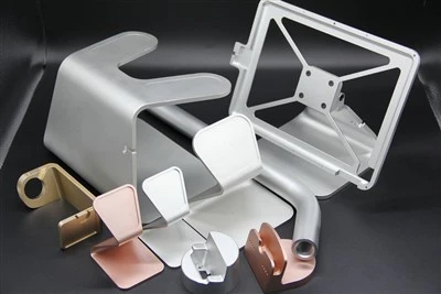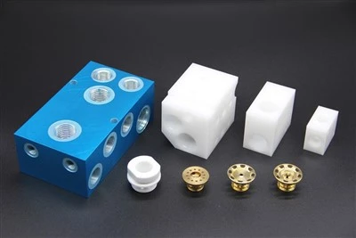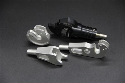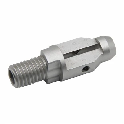

Complex Geometry Capabilities
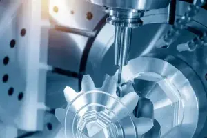
The biggest challenge of complex milling components lies in the complexity of their geometric shapes. Many factories choose to decline when faced with deep cavities, thin walls, irregular surfaces, or concave features, but we consider them as everyday talents.
We can stably process the following high difficulty features:
industry-leading
Deep cavity machining: depth to diameter ratio>10:1, equipped with specialized extended cutting tools and vibration suppression plan
01
High market share
Thin walled structure: The thinnest wall is only 0.3mm thick, and after optimizing the cutting path and layered milling, deformation is effectively controlled
02
High market share
Irregular surfaces: high-precision machining of free-form surfaces, complex flow channels, blade profiles, etc
03
Perfect product system
Undercut feature: Completed in one go using a 5-axis swing head or specialized molding tool
04
Efficient after-sales service
Micro features: minimum aperture of Φ 0.5mm, fine boring and milling composite process
05
Composite material hybrid: Metal inserts and hard alloy partially reinforced areas are securely separated
Case 1: Aircraft titanium alloy thin-walled bracket
- Difficulty: Wall thickness of 0.35mm, multiple deep cavities, prone to vibration deformation.
- Our plan: 5-axis linkage+dynamic tool path optimization+low-temperature cooling.
- Result: The average wall thickness was ± 0.02mm, and it successfully passed the customer's rigorous vibration test.
Case 2: Irregular flow channel components of semiconductor equipment
- Difficulty: The internal flow channel surface is complex, and the required surface roughness is Ra0.4 μ m.
- Our plan: simultaneous 5-axis milling+specialized ball head cutting tools.
- Result: The surface of the flow channel is lubricated without any cutting marks and has undergone a cleanliness test once.
Complex features can be compared to the table:
|
Complex Feature Type |
Industry Standard Limit |
Our Capability |
Typical Materials |
|
Deep Cavity Aspect Ratio |
6:1 |
10:1 |
Aluminum / Steel / Titanium |
|
Minimum Wall Thickness |
0.5mm |
0.3mm |
Aluminum Alloy |
|
Minimum Hole Diameter |
Φ1.0mm |
Φ0.5mm |
Stainless Steel |
|
Freeform Surface Accuracy |
±0.05mm |
±0.01mm |
Titanium Alloy |
Through the above abilities, we have successfully landed many complex CNC milling parts that were originally "impossible to machine".
5-Axis Machining Assessment
5-axis milling components are not necessary for all parts, but when your design includes multi-directional features or high-precision requests, 5-axis linkage is often the best or even the only processing plan.
Under what circumstances is 5-axis machining required?
The following feature discrimination checklist can assist you in quickly evaluating:
Parts have machining features in two or more directions
Complex surfaces that cannot be reached through 3+2 positioning
Coaxiality, perpendicularity and other positional tolerances are requested to be less than 0.01mm
Reduce the demand for thin-walled parts by repeatedly clamping to control deformation
Typical curved parts such as impellers, blades, and complex flow channels
Our 5-axis CNC machining capabilities
We are equipped with high-end simultaneous 5-axis milling centers such as DMG MORI and Hermle, using a dual structure of swing head and turntable, which can sensitively respond to different part configurations. The maximum processing envelope size is 800 × 600 × 500mm, and the maximum load-bearing capacity is 300kg.
The biggest advantage lies in the one-time clamping completion rate: the number of clamping for complex parts has been reduced from the traditional 4 or more times to 1, and the position accuracy has been improved by about 60%, effectively preventing error accumulation.
Comparison Table of 3-axis vs 5-axis Machining
|
Evaluation Dimension |
3-Axis Solution |
5-Axis Solution |
Advantage Description |
|
Feature Complexity |
Single-direction features |
Multi-direction / Complex surfaces |
Much wider range of applicable geometries |
|
Number of Setups |
Multiple setups (error accumulation) |
Single setup (higher accuracy) |
Significantly reduces positioning errors |
|
Processing Cost |
Lower initial cost |
Higher per setup, but lower overall cost |
Saves secondary operations and inspection |
|
Suitable Applications |
Simple prismatic parts |
Complex curved surfaces, aerospace, medical parts |
Higher efficiency and precision in one pass |
Correction of common misconceptions among customers
- Misconception 1: "As long as a part has a curved surface, it must use 5 axes" - some regular surfaces can be efficiently completed using 3+2 positioning.
- Misconception 2: "5-axis machining is too expensive" - In fact, reducing the number of clamping times and secondary machining can often significantly reduce overall costs.
We will objectively recommend the most economical and reasonable multi axis milling components processing plan based on the characteristics of the parts.
DFM Analysis
Design for manufacturability CNC is crucial in the production of complex parts. According to statistics, 70% of the production cost has already been determined during the planning stage. Early DFM analysis can effectively prevent rework and cost waste in the later stage.
Common DFM Issues and Results
Excessive public service labeling → Excessive processing costs by 30-50%
Unnecessary deep cavities or indentations → tool interference, increased machining difficulty
The inner corner radius is too small → the tool cannot move, resulting in the inability to process
Surface roughness requirements do not match actual functionality → unnecessary post-processing is added
Our DFM analysis process
- Upload drawings (supporting STEP, IGES, DXF formats)
- Senior engineer completes DFM analysis machining within 24 hours
- Provide a detailed DFM report (identifying problem points+optimization proposals+cost impact assessment)
- Communicate with the client to confirm the modification plan
After optimization, it officially enters production
The DFM report includes: identification of non processing features, evaluation of service rationality, material selection proposals, analysis of surface treatment compatibility, and estimated cost savings.
Real DFM optimization case
A certain airline customer submitted a detailed bracket plan, but the original image had 3 concave features that could not be processed, and multiple public service markings were too strict. After our intervention, we optimized the R value of the inner fillet, relaxed the public service of non fitting surfaces, and adjusted the clamping benchmark. Final result: The parts have changed from 'unable to produce' to smooth mass production, with a 22% reduction in cost per unit and a 5-day shortened lead time.
Through free DFM analysis, we have helped many clients turn the planning of complex milling components into truly producible high-quality products.
Quality Consistency
Our consistency assurance system
Consistent quality CNC parts are the most difficult bottleneck to break in the chaotic milling of parts. The problems of tool wear, thermal deformation, and repetitive clamping often lead to batch loss of control after the first piece is qualified.
Processing of tool lifespan:
Real time monitoring by CNC system, setting mandatory tool change nodes
Standardization of fixtures:
specialized fixtures are reused, with a fixture repeatability of<0.003mm (reproducible CNC machining)
SPC process calculation control:
real-time monitoring of key dimensions, timely warning of abnormalities
CMM testing plan:
Provide a complete testing statement for each batch
Advanced detection capability
Coordinate Measuring Machine (CMM):
Measurement accuracy ± 0.001mm
Blue light scanner:
Detection of irregular curved surfaces and full surfaces
Contour and roughness meters:
Ra/Rz full parameter masking
Impression measuring instrument: high-precision 2D detection of small features
Quality Data Certification
Customer inspection pass rate:
99.2%
Cpk value of inter batch size:
≥ 1.33
Quality complaint rate:
<0.5%
We can provide PPAP, FAI first article statements, material certificates, and full-size inspection statements according to demand.
Certification Wall: ISO 9001:2015, IATF 16949 As a professional precision milling supplier, we provide you with quantifiable data and rigorous systems for every batch of complex milling components.
FAQ
Hot Tags: complex milling components, China complex milling components manufacturers, suppliers, factory, Aluminum CNC Machining Service, Complex Milling Components, Delrin Machined Parts, High Tolerance Milling, On demand CNC Machining, Stainless Steel Milling Parts