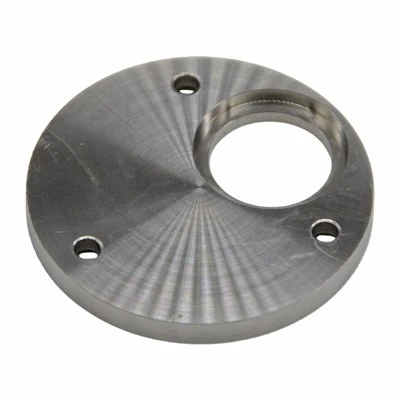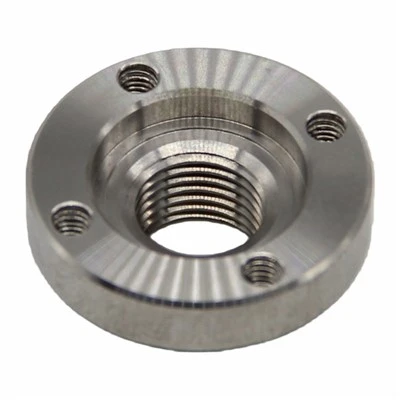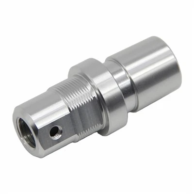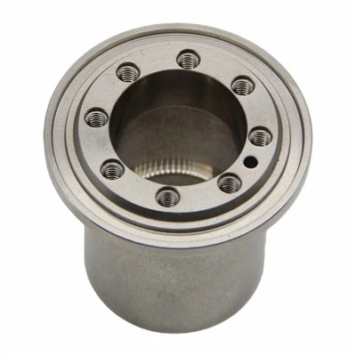

A drawing with angled holes, deep cavities, or curved surfaces often gets labeled as a five-axis job before anyone reviews the process. Sometimes that is the right call. In other cases, the extra machine capability adds cost without improving the part. The value of 5 axis machining comes from better tool access, fewer setups, and tighter control of features that would otherwise be split across several operations.
A flat bracket gains little from being placed on a five-axis machining center. An impeller, multi-port housing, thin-walled medical component, or part with features on several compound angles presents a different problem. Repeated removal and realignment on a three-axis machine can add time, fixtures, and positional variation. For these parts, 5 axis cnc machining services may simplify the complete route rather than merely replacing one machine with another.
What the Five Axes Actually Do
A three-axis mill moves along the X, Y, and Z linear axes. A five-axis machine adds two rotary movements, allowing the tool to approach the workpiece from different orientations. Depending on the machine design, the table may rotate, the spindle head may tilt, or both may move.
Those rotary axes make it possible to cut several sides of a component while preserving one established datum. A side hole, angled sealing face, and top pocket can potentially be produced without removing the part and locating it again. Fewer setups help maintain the positional relationships between those features.
One setup does not mean that every five-axis part goes from raw stock to finished component in a single uninterrupted operation. Roughing, stress relief, access to the underside, heat treatment, and final finishing may still require planned transfers. The aim is to remove unnecessary repositioning while keeping the process stable.
3+2 Machining and Simultaneous Five-Axis Motion
The term 5 axis cnc machining covers two different approaches. In 3+2 work, the rotary axes first position the part at a chosen angle. They then remain fixed while the X, Y, and Z axes perform the cut. The machine can index to another angle for the next group of features.
This method works well for multi-sided parts, angled holes, chamfers, and surfaces that can be reached from a series of fixed directions. Programming and verification are generally more direct than full simultaneous motion, and many parts described as five-axis components can be produced efficiently this way.
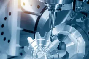
In continuous five-axis machining, all five axes can move together while the tool is cutting. The tool angle changes along the path, making the method suitable for impellers, blades, flowing channels, undercuts, and free-form surfaces.
The two methods should not be treated as interchangeable names. A component with five fixed machining directions may need 3+2 positioning, while a smoothly changing aerodynamic surface can require simultaneous motion. If a buyer specifies "five-axis" without explaining the geometry or process requirement, the supplier still has to determine which approach makes sense.
Why Fewer Setups Can Improve Accuracy
Every new setup requires the workpiece coordinate system to be established again. Fixture location, datum quality, probing, clamping, and handling introduce small variations. A single variation may be acceptable, but a chain of setups can affect the final relationship between holes, faces, and profiles.
Consider a valve housing with a locating bore on the front and an intersecting passage entering from an angle. If the two features are machined in separate fixtures, their relationship depends on the accuracy of the second location. With suitable 5 axis milling, the tool can approach the angled passage while the original datum remains active.
Small batches can benefit as well. A conventional route may need several dedicated fixtures for different sides of the part. A five-axis table can replace some of those fixture orientations, reducing preparation time and the fixed cost attached to a short run. The actual saving depends on the program, workholding, and inspection plan; higher machine rates alone do not reveal the total part cost.
Five-Axis Equipment Does Not Guarantee a Tight Tolerance
A machine with five controlled axes still cuts a real material held by a real fixture. Part size, wall thickness, tool reach, cutting force, material stress, temperature, and inspection uncertainty remain part of the result. The machine configuration improves access and setup control, but it cannot make those conditions disappear.
Multi-Wins publishes a standard tolerance of approximately ±0.025 mm on its general service page, with tighter requirements reviewed by project. Its continuous machining page lists linear tolerance capability around ±0.0127 mm for selected equipment and processes. Other precision milling work may support tighter local features when geometry, material, fixturing, and measurement allow it. These figures belong to different operating conditions and should not be merged into one universal promise.
When a drawing calls for ±0.005 mm, the first question is where that tolerance applies. A short bore, deep-cavity floor, large thin wall, and free-form profile present very different control problems. A qualified provider of 5 axis machining services will review the feature and datum rather than quote the smallest number on the drawing as if it applied equally everywhere.
Geometric tolerances deserve the same attention. Profile, position, flatness, runout, and perpendicularity may matter more than a simple plus-or-minus dimension. The inspection plan must be able to reproduce the datum system used on the drawing, or the reported result will be difficult to interpret.
Tool Orientation Is a Major Part of the Advantage
Deep cavities and angled surfaces often force a three-axis process to use long tools. As tool overhang increases, rigidity drops and the cutter becomes more sensitive to vibration and deflection. The result may be chatter, poor finish, or a conservative cycle with light cuts.
Five-axis motion can tilt the part or spindle so that a shorter cutter reaches the same feature. A shorter tool is generally stiffer, giving the process more room to control cutting force and surface finish. The programmer can also use the side of a ball or bull-nose tool instead of leaving the low-surface-speed center of the tip on the workpiece.
On a free-form surface, tool orientation affects cusp height and visible tool marks. Simultaneous 5 axis machining can maintain a more favorable contact angle as the surface changes. That may reduce hand polishing, though the final result still depends on the cutter, step-over, feed, toolpath smoothing, and material.
Collision avoidance becomes more demanding at the same time. The tool tip may clear the part while the holder, spindle head, rotary table, or fixture does not. CAM simulation should cover the complete machine movement, not only the programmed cutter path.
Parts That Commonly Suit 5 Axis Milling
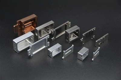
The strongest candidates for 5 axis milling combine several directions, changing surfaces, difficult access, or strict positional relationships. Typical examples include impellers, turbine blades, aerospace brackets, robotic joints, medical instrument components, performance automotive parts, semiconductor equipment parts, and precision housings.
These components may contain deep internal features, compound-angle holes, thin walls, undercuts, or several machined faces related to one datum. A five-axis route can reduce the number of times those relationships are transferred between fixtures.
Simple plates, open pockets, and regular prismatic parts often remain better candidates for three-axis or four-axis equipment. Rotational components may be more economical on a CNC lathe or turn-mill center. The correct machine follows the geometry; the product category should not dictate the process before the drawing is reviewed.
Material Changes the Machining Strategy
Aluminum alloys are widely used in aerospace structures, electronics, robotics, and automation equipment. Grades such as 6061 and 7075 differ in strength, residual stress, availability, and finishing behavior. A complete RFQ should state both the alloy and temper.
Titanium alloys combine strength with low thermal conductivity, so cutting heat remains concentrated near the tool. A favorable five-axis tool angle can help manage engagement, but cutting speed, coolant, coating, and toolpath still need careful control. Inconel and other heat-resistant alloys impose even higher demands on tool life and machine time.
Stainless steels such as 304 and 316 can work-harden when the tool rubs or engagement becomes unstable. Deep cavities and thin sections require planned cutting sequences and reliable coolant. Engineering plastics such as POM and PEEK create lower cutting forces, yet temperature, clamping pressure, moisture response, and internal stress can affect dimensions after machining.
There is no single five-axis program that can be transferred unchanged between these materials. Tool selection, spindle speed, feed, cooling, workholding, and inspection must be adjusted to the material and feature.
Thin Walls and Deep Cavities Need More Than Access
Thin walls can move under both clamping and cutting force. A dimension may appear correct while the part is held and then change after release. Symmetrical stock removal, staged roughing and finishing, local support, and low-force toolpaths may be needed to control the final shape.
Deep cavities bring a different mix of problems. Five-axis tilting can reduce tool overhang, but chip evacuation and heat remain difficult inside a confined space. The program also has to account for clearance between the workpiece, holder, spindle, and machine structure throughout the tilt range.
Problems often overlap. A titanium blade combines heat, vibration, and a thin section. A deep aluminum housing may combine long internal walls with side features and restricted chip flow. The 5 axis cnc machining strategy has to address the complete part rather than one attractive feature in isolation.
DFM Review Before Programming
Five-axis capability expands what can be reached, but it does not make every design efficient. A cavity may still be too deep for a practical tool. An internal corner may require an extremely small cutter. A thread may lack entry or runout space, and a critical surface may be difficult to measure after machining.
Design-for-manufacturing review checks tool access, rotary-axis travel, collision risk, tolerance logic, stock choice, datum planning, workholding, and inspection. It also identifies design changes that can lower risk without changing function.
Increasing one noncritical radius may allow a shorter, stronger standard tool. Changing the direction of a hole may remove a special operation. Adding a temporary clamping feature can stabilize a thin part and be removed later. These are small drawing changes with a direct effect on cycle time and repeatability.
DFM has to happen before the quote and program are fixed. Once parts have been cut, a manufacturability discussion has arrived too late to prevent the original cost.
From Prototype to Repeat Production
Many 5 axis cnc machining services begin with prototypes or a short validation batch. At that stage, the objective is to verify geometry, assembly, and performance. Flexible fixtures and extra operator attention may be reasonable because the team is still learning about the part.
Production needs another review after sample approval. Fixture repeatability, tool-life limits, probing routines, in-process inspection, material lots, and handling between operations become more important as quantity increases. A method that works for three prototypes may depend too heavily on manual adjustment for a recurring order.
First-article inspection confirms the starting setup. It cannot describe how the process changes as tools wear, the machine warms, and material batches vary. Critical features need a measurement frequency and a response plan. For complex surfaces, CMM inspection may be required to compare the manufactured profile with the nominal CAD geometry.
Revision control is equally practical. The drawing, 3D model, purchase order, inspection program, and shop traveler should identify the same version. When a design changes, old files must leave the active process. A precise machine cannot compensate for an outdated model.
What to Include in a Five-Axis RFQ
A 3D model shows the shape, but it usually does not carry every acceptance requirement. Send a PDF engineering drawing with the STEP or other suitable model, and make sure the revision matches.
The RFQ should identify:
- Material grade, condition, and permitted substitutions
- Prototype quantity, production quantity, and expected annual demand
- Datums, critical dimensions, fits, and geometric tolerances
- Surface roughness, heat treatment, and finishing
- Features tied to assembly, sealing, flow, or motion
- Inspection reports, material certificates, and traceability
- Cosmetic limits, packaging, and delivery requirements
- Whether 3+2 or simultaneous five-axis motion is mandatory
The last item should be specified only when the process itself matters. If the contract is based on the finished part, the supplier may be able to choose a more economical combination of three-axis, 3+2, simultaneous five-axis, turning, grinding, or EDM. When certification or an approved route requires a particular process, that condition belongs in the original RFQ.
Reading a 5 Axis Machining Quote
Five-axis machine time usually costs more than basic three-axis time, but hourly rate is only one element. A shorter route may eliminate fixtures, intermediate inspection, setup labor, and queue time between machines. For a complex part, the total may be lower even when the machine-hour rate is higher.
Material, programming, simulation, tool consumption, workholding, cycle time, inspection, finishing, and scrap risk all affect the quote. A titanium impeller and aluminum multi-sided housing can be similar in size and completely different in cost. Complex surfaces also require more CAM preparation and verification than a set of fixed drilled faces.
Comparable quotes must share the same assumptions. Check material condition, quantity, tolerance interpretation, included reports, finish, packing, and delivery. If one supplier assumes standard tolerance while another prices a fully documented profile inspection, the unit prices do not represent the same job.
Use Five Axes Where the Process Benefits
5 axis cnc machining is useful for compound angles, spatial surfaces, deep cavities, multi-sided hole patterns, and parts that lose accuracy through repeated setups. It also gives the programmer more control over tool reach and contact angle. Simpler parts can still be produced more economically on three-axis, four-axis, or turning equipment.
Multi-Wins provides 3+2 positioning and simultaneous 5 axis machining services for aluminum, stainless steel, titanium, heat-resistant alloys, and engineering plastics. Available equipment, travel, tolerance, finish, and lead time are reviewed against the actual drawing because different machines and part structures support different limits.
Send the material, quantity, tolerance, inspection, and finishing requirements together when you request a project quotation. That information gives the engineering team enough context to decide whether five-axis work is necessary and which form of it fits the component.
The strongest 5 axis machining project is defined by a short, stable, and measurable process. Machine capability matters, but the result still comes from sound datum planning, tool access, workholding, programming, and inspection.
Tags: 5 axis machining, 5 axis cnc machining, 5 axis cnc machining services, 5 axis milling, 5 axis machining services