
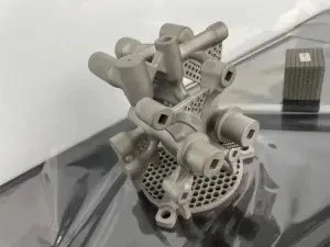
Complex Internal Flow Channels
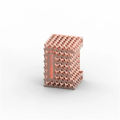
Metal additive manufacturing frees internal passages from the limits of a drill bit. Designers can create smooth curves, gradually changing cross-sections, and channels that follow the outer geometry or track heat loads. The flow becomes cleaner: lower pressure drop, more uniform velocity, reduced turbulence, and fewer pockets where fluid can stagnate or leave residue.
Surface quality and powder removal are handled with equal care. Minimum channel diameters are normally held between 1 mm and 2 mm, adjusted for length and complexity. Longer or tightly curved routes include dedicated exit ports and self-supporting angles so residual powder can leave the part. After the build we use vibration, high-pressure air or inert-gas flushing, and ultrasonic cleaning when required. Industrial CT scanning (where part size and density allow) confirms every passage is open; accessible ports also receive a borescope check. These design rules and verification steps make reliable internal flow channels possible with metal 3D printing on production parts.
Part Integration
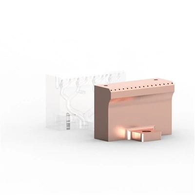
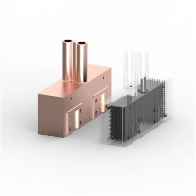
A single metal 3D printed manifold can incorporate valve blocks, tube connectors, mounting brackets, sensor bosses, and filter housings. Part count drops sharply, most external seals and welded joints disappear, system weight falls, and assembly time shrinks. The monolithic structure also gains stiffness and handles vibration better.
Side by side the difference is clear:
Traditional multi-piece build: 8–15 separate components, extra mass from material and fasteners, 6–12 leak interfaces, weeks of tooling and assembly.
Integrated design via additive manufacturing: one component, typical mass reduction of 20–40% when topology optimization is applied, only the external sealing faces remain, delivery in 7–15 working days for prototypes and small runs.
Teams that move to an integrated hydraulic manifold produced by 3D printing usually see the largest gains in reliability and total installed cost.
Custom Metal 3D Printed Manifold Prototypes

The process starts with a drawing or STEP file. We perform a design-for-additive review covering orientation, supports, channel access, and critical tolerances. The part is built on industrial laser powder-bed fusion (LPBF / SLM) systems. Post-processing includes stress-relief heat treatment, support removal, and CNC finishing of sealing faces and threads. Pressure or helium leak testing plus dimensional inspection complete the sequence before shipment. Approved designs move directly into low-volume production without new tooling.
Typical lead time for custom metal 3D printed manifold prototypes is 7–15 working days from approved design to shipped part. Materials kept in regular stock include:
316L stainless steel - good corrosion resistance for water, mild chemicals, and common hydraulic fluids
AlSi10Mg - high thermal conductivity and low mass for cooling circuits and lightweight pneumatic manifolds
Ti6Al4V - high strength-to-weight ratio and biocompatibility for aerospace and medical fluid systems
Inconel 718 - high-temperature and corrosion performance for aggressive media or elevated operating temperatures
As a specialized metal additive manufacturer we run both one-off prototypes and small series under the same process controls.
Key technical specifications
Maximum build envelope: up to 250 × 250 × 300 mm (larger parts possible via multi-piece strategies)
Typical dimensional tolerance: ±0.1–0.2 mm after CNC finishing of critical features
Internal channel surface roughness: Ra 6–15 µm as-built; lower values achievable with post-processing
Minimum wall thickness: 0.8–1.0 mm (geometry- and material-dependent)
Working pressure: material- and design-dependent; routinely validated up to several hundred bar with proof and burst testing
Accepted file formats: STEP, IGES, Parasolid, and native CAD
Industries and Applications
Hydraulic and pneumatic systems replace bulky valve blocks with compact circuits that respond faster and waste less energy. Semiconductor equipment uses these manifolds for ultra-clean gas and liquid lines where particle generation and dead volume must stay near zero. Electric-vehicle thermal management integrates conformal cooling channels directly into battery cold plates or power-electronics housings. Aerospace applications include fuel-distribution and engine-cooling manifolds that reduce weight while meeting certification requirements. Robotics benefits from lightweight multi-function fluid manifolds that free payload capacity. Medical devices and laboratory instruments rely on compact fluid handling with minimal residual volume.
Quality Assurance
We operate multiple industrial laser powder-bed machines dedicated to metal components. Every batch is accompanied by material certificates of analysis. Verification includes industrial CT scanning where part size and density allow, hydrostatic or pneumatic pressure testing, helium leak testing when specified, and CMM checks on critical features. Quality management processes are aligned with ISO 9001 practices.
In a recent project for an industrial automation customer, an 11-piece hydraulic manifold was redesigned as a single metal 3D printed manifold in 316L. Part count fell from 11 to 1, assembly time was reduced by more than half, six potential leak points were eliminated, and functional prototypes were delivered in under two weeks. The customer's subsequent pressure and cycle testing confirmed performance.
FAQ
Q: Can manifolds be 3D printed in metal?
A: Yes. Laser powder-bed fusion (LPBF / SLM) builds complex internal channels and integrated features as one piece from alloys such as 316L, AlSi10Mg, titanium, and nickel-based superalloys.
Q: Are metal 3D printed manifolds strong enough for high-pressure applications?
A: When wall thickness, material, and post-processing are correctly specified, fully dense parts routinely support several hundred bar. Proof and burst testing are performed on request.
Q: What is the minimum internal channel diameter you can print?
A: Typically 1–2 mm for shorter passages. Longer or highly curved channels may require slightly larger diameters or dedicated powder-evacuation features to ensure complete cleaning.
Q: How do you remove powder from complex internal channels?
A: Designed evacuation ports, mechanical vibration, high-pressure air or inert-gas flushing, and ultrasonic or chemical cleaning when required. CT (where applicable) or endoscopic inspection confirms the passages are clear.
Q: What materials do you offer for 3D printed manifolds?
A: 316L stainless steel, AlSi10Mg aluminum, Ti6Al4V titanium, and Inconel 718. Selection depends on corrosion resistance, temperature, weight, and media compatibility.
Q: Do you accept low-volume orders?
A: Yes, with no minimum quantity.
Q: What is the typical lead time for prototypes?
A: 7–15 working days from approved design to shipped part, depending on complexity and finishing requirements.
Hot Tags: metal 3d printed manifolds, China metal 3d printed manifolds manufacturers, suppliers, factory, 3d metal casting, 3d printing and casting, 3d printing casting, 3d printing metall, metal printing at home, metal printing services