
Heating Efficiency & Performance
Induction heating relies on eddy currents and the skin effect to heat the workpiece. Coil geometry directly shapes the magnetic-field distribution, which in turn governs heating uniformity. Round-tube coils, limited by tube-bending constraints, often produce uneven fields.
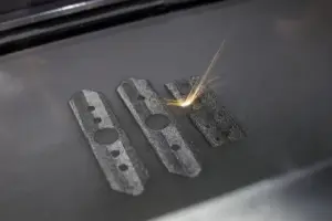
Additive manufacturing enables D-shaped, square, and fully customized cross-sections that improve flux concentration on the work zone. In our customer programs and internal benchmarks, optimized AM coil geometries typically improve heating efficiency by 10–25% versus comparable brazed-tube coils, with measurable gains in heating uniformity and thermal-cycle life.
Performance Comparison
|
Parameter |
Traditional Copper Coil |
3D-Printed Induction Coil |
Typical Improvement |
|
Heating Uniformity (peak-to-peak ΔT) |
±15–20% |
±5–10% |
≈50–70% reduction |
|
Surface Power Density (kW/cm²) |
0.5–2 |
1–4 |
Up to 2× higher |
|
System Energy Efficiency |
60–75% |
75–88% |
+10–15 pts |
|
Coil Service Life (thermal cycles) |
Baseline |
≈2× baseline |
Up to 2× longer |
Comparisons depend on workpiece geometry, frequency, and duty cycle. Power-density ranges reflect typical surface-hardening duties; values must be re-validated for each application via electromagnetic simulation.
Cooling Capability
High-power coils dissipate significant ohmic heat in the copper itself. Without adequate cooling, the copper softens, insulation degrades, and the coil fails. Traditional brazed or wound coils rely on straight or simply-bent tubing, leaving uneven flow and hotspots.
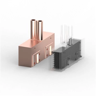
3D-printed induction coils use conformal cooling channels that follow the contour of the heating surface. This places coolant where heat actually accumulates, improving temperature control and supporting sustained higher-power operation.
Typical cooling capabilities:
Minimum self-supporting cooling channel diameter: ~1.5 mm
Optimized water flow rates and channel routing for uniform heat extraction
Coil-surface temperature reduction of 20–50 °C versus comparable brazed coils at equal load (geometry-dependent)
Cooling Performance Comparison
|
Feature |
Traditional Brazed Copper Tube |
3D-Printed Induction Coil |
|
Channel Geometry |
Straight or simply bent |
Conformal to heating surface |
|
Joint Count |
Multiple brazed joints (leak risk) |
Monolithic - no internal joints |
|
Flow Uniformity |
Uneven |
Optimized via simulation |
|
Service Life |
Baseline |
≈2× baseline (typical) |
CFD simulation and thermal imaging consistently confirm the cooling advantage, and design qualification follows ASTM and ISO methods relevant to thermal management systems.
Material Properties
We primarily use pure copper (≥99.9% Cu) for induction coils. After post-processing, electrical conductivity reaches 95–98% IACS - close to wrought copper. Thermal conductivity (~390 W/m·K) supports efficient heat dissipation, while low resistivity preserves induction efficiency.
Material Comparison
|
Property |
Pure Copper (3D Printed) |
Beryllium Copper (BeCu) |
CuCrZr Alloy |
Brass (Typical) |
|
Electrical Conductivity (% IACS) |
95–98% |
15–45% |
75–85% |
26–28% |
|
Thermal Conductivity (W/m·K) |
~390 |
~105–230 |
~320 |
~109–121 |
|
Tensile Strength (MPa, post-processed) |
200–260 |
410–1380 |
300–500 |
310–550 |
|
Best Fit for Coils |
Highest efficiency |
High strength |
Strength + conductivity |
Lower cost |
As-printed pure copper can show higher tensile strength (~300–350 MPa) but lower conductivity and ductility; values above are for the HIP + annealed delivery condition recommended for most coil applications.
Pure copper remains the preferred coil material when peak heating efficiency is required. With HIP and annealing, AM copper density reaches >99.5%, and performance approaches that of wrought copper.
Design Capability
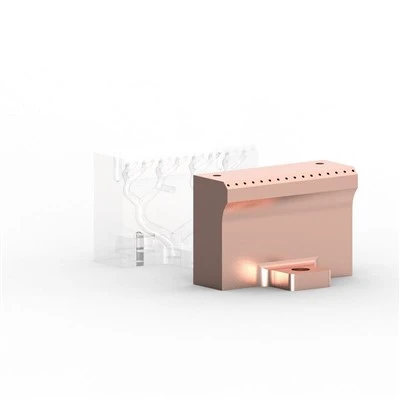
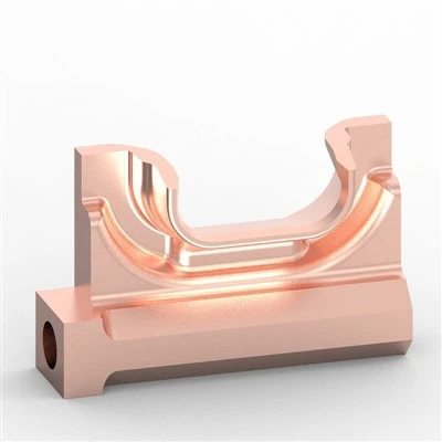
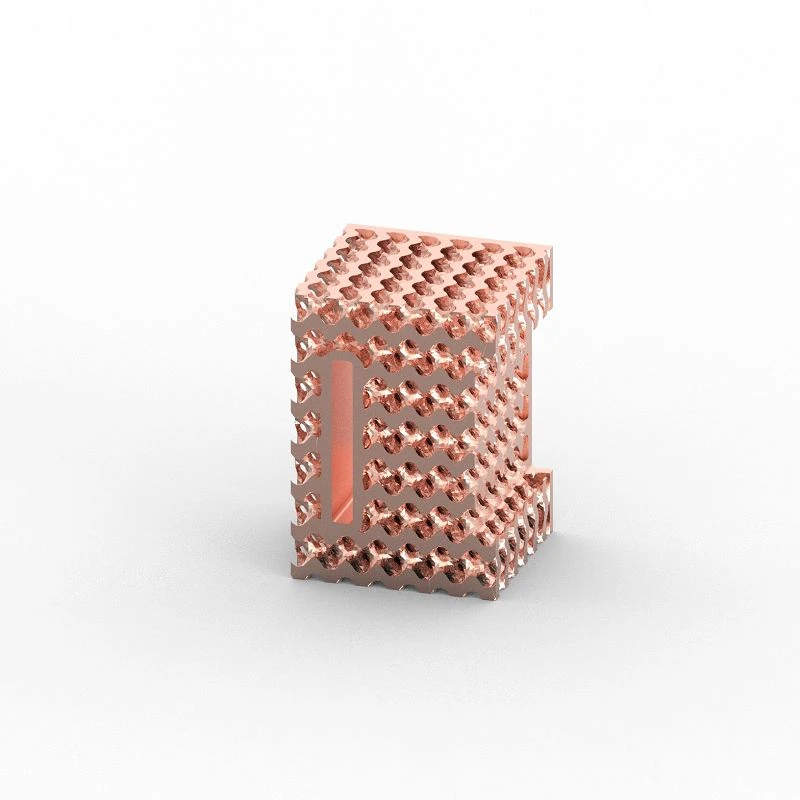
3D-printed induction coils support extreme geometric complexity: single-turn, multi-turn, helical, variable cross-sections, and integrated conformal cooling - all in one monolithic part.
Key advantages over traditional manufacturing:
Elimination of internal brazed joints - reduced leak risk and improved mechanical integrity
Topology-optimized shapes for better magnetic-field shaping
Full DFM support including FEA electromagnetic and thermal simulation
Technical specifications:
Dimensional accuracy: ±0.1 mm on typical features
Minimum wall thickness: 0.4 mm
Minimum internal cooling channel diameter: 1.5 mm
3D Printing Processes for Induction Coils
|
Process |
Best Use Case |
Notes |
|
Laser Powder Bed Fusion (LPBF) |
Highest-precision small to medium coils |
Best resolution and tightest tolerances; preferred for micro-electronics coils |
|
Binder Jetting (BJT) |
Complex internal cooling, mid-volume production |
Good balance of surface finish and internal-channel complexity; requires sintering |
|
Directed Energy Deposition (DED) |
Large coils or repair of high-value assemblies |
High deposition rate; ideal for cladding and component repair |
Recommendation: For most industrial hardening and brazing coils, LPBF in pure copper offers the best combination of conductivity, internal-channel quality, and dimensional control. Binder jetting is attractive when production volume and channel complexity are both high.
Post-Processing for Coil Performance
The as-printed state is a starting point. To make AM induction coils survive industrial heat-treatment environments, we apply a multi-stage post-processing workflow:
Vacuum Sintering (BJT only) - Achieves full density and target IACS conductivity after binder burnout.
Hot Isostatic Pressing (HIP) - Closes residual microporosity; improves density and fatigue life.
Hydrogen or Inert-Atmosphere Annealing - Relieves residual stress and restores ductility, reducing crack risk under thermal cycling.
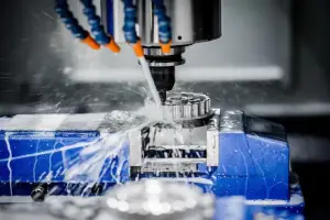
Precision CNC Machining - Tightens tolerances on critical mating surfaces, typically to ±0.01 mm.
Surface Treatment - Silver plating to reduce skin-effect losses at high frequencies, or electroless nickel plating for corrosion resistance in harsh cooling-water environments.
Customization Service
We offer end-to-end custom copper induction coil services:
- Requirements discussion and concept development
- DFM review with electromagnetic and thermal simulation
- 3D printing in pure copper
- Post-processing (HIP, annealing, machining, surface finishing)
- Inspection, testing, and delivery with Certificate of Conformance and dimensional reports
Customization options include:
▲ Outer dimensions, number of turns, cross-section profile
▲ Conformal cooling-channel layout and connection types (threaded, flanged, quick-connect)
▲ Surface finishes and plating
Lead times: 5–10 working days for standard designs; 10–15 working days for highly customized coils. Minimum order quantity: 1 piece.
Field Results
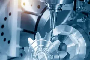
♦ Automotive case: An EV Tier-1 supplier replaced a brazed assembly with our monolithic AM coil for gear hardening, reducing cycle time by ~12% and removing leak points at brazed joints.
♦ Aerospace application: A custom-profiled coil for turbine-blade brazing achieved heating uniformity within ±5% across the work zone in customer testing.
Field results are program-specific and depend on workpiece geometry, frequency, and process controls; we replicate the qualification process for each new application rather than guaranteeing the same numbers in a different system.
FAQ
Hot Tags: 3d printed induction coils, China 3d printed induction coils manufacturers, suppliers, factory, 3D Printed Heat Exchangers, 3D Printed Induction Coils, Copper Additive Manufacturing, Industrial Metal 3D Printing, metal 3d printing, Pure Copper 3D Printing