

Machining Scope
CNC milling is not meant to replace every kind of machining task - it is best applied where its programmable, multi-axis, high-precision capabilities offer a real advantage over conventional (manual) milling. The typical machining scope for CNC milling includes the following categories:
Curved contours on a workpiece: straight lines, circular arcs, threads or helical curves, and - especially - non-circular curves and tabulated (list-defined) curves that are given by mathematical expressions. These are exactly the kinds of profiles that are extremely difficult, or practically impossible, to machine accurately by hand on a conventional milling machine, since a manual operator has no reliable way to continuously trace a curve defined by a formula. A CNC controller, by contrast, can interpolate along these mathematically defined paths point by point with high positional accuracy, which is precisely why such contours are considered core CNC milling territory.
Spatial curves or curved surfaces for which a mathematical model has already been established. Once a surface or curve has been defined mathematically - whether through explicit equations, parametric definitions, or a set of coordinate data points - CNC programming software can convert that model directly into a toolpath. This makes CNC milling the natural choice whenever design data already exists in digital, mathematically describable form, since the machining process can inherit the same precision that went into the mathematical definition itself.
Areas that are geometrically simple in shape but involve numerous dimensions and are difficult to inspect. Even a part that looks straightforward on paper can become a serious burden for the operator if it has a large number of individual dimensions that all need to be measured and verified. CNC milling reduces this burden because the machining sequence and dimensions are controlled directly by the program, cutting down on manual measurement steps and the risk of cumulative error that comes from repeated manual positioning.

Internal cavities, box-type interiors, and similar features that are difficult to observe, control, and inspect when machined on a conventional machine tool. On a manual machine, the operator typically relies on direct visual observation and hand-feel to judge progress and accuracy. Enclosed cavities and internal box structures are, by nature, hard to see into during the cut, which makes manual control unreliable. A CNC machine does not depend on the operator's line of sight - the tool follows a pre-programmed path with a known, repeatable trajectory, which makes it far better suited to producing accurate internal geometry that a person could not easily monitor by eye.
Holes or flat surfaces that carry strict dimensional requirements. Where a hole diameter, a flatness tolerance, or a positional tolerance must be held to a tight range, the repeatability of CNC positioning and feed control offers a level of consistency that is difficult to guarantee through manual operation, especially across a batch of parts.
Simple surfaces or shapes that can be conveniently machined along the way, within the same clamping setup as other features. If a workpiece is already clamped and being machined for its primary features, it often makes sense to let the CNC program also complete any small, simple, incidental surfaces or shapes in the same setup, rather than requiring a separate operation or a different machine - this saves setup time and avoids introducing new positioning error.
General machining content where the use of CNC milling can meaningfully improve production efficiency and reduce labor intensity, even if the content itself is not particularly complex. In other words, CNC milling is not reserved only for geometrically difficult work - it is also justified whenever it offers a clear productivity or ergonomic benefit compared to conventional methods, such as reducing operator fatigue on repetitive tasks or shortening cycle time through faster, more consistent tool paths.
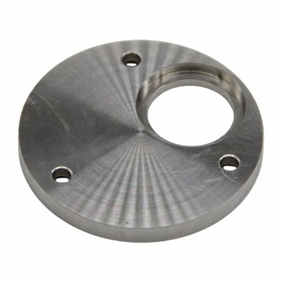
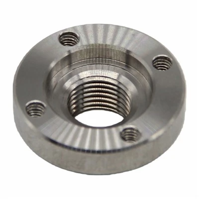
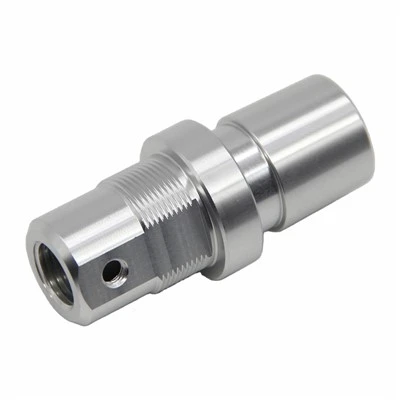
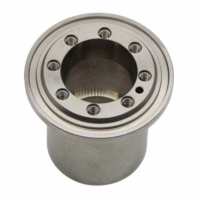
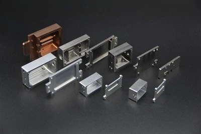
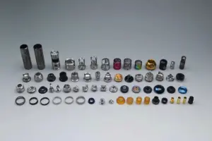
Taken together, the main categories of parts that are well suited to CNC milling fall into four broad groups: planar-contour parts, variable-bevel-angle parts, spatial-curved-surface-contour parts, and parts featuring holes and threads.
Supplementary Information
As noted above, the main machining objects suited to CNC milling are planar-contour parts, variable-bevel-angle parts, spatial-curved-surface-contour parts, and parts with holes and threads. Each of these categories has its own defining characteristics worth examining in more detail.
Planar-Type Parts

Planar-type parts are characterized by machined surfaces that may be parallel to the horizontal plane, perpendicular to the horizontal plane, or set at a fixed angle relative to the horizontal plane. The defining feature is that, regardless of orientation, each individual surface remains a flat plane rather than a curved one - the plane itself may sit at any angle in space, but it does not bend or curve within itself.
The vast majority of parts encountered in practice fall into this planar category, making it the most common - and generally the simplest - class of parts handled in CNC milling. Because these surfaces are geometrically flat rather than continuously curved, machining them usually does not require full simultaneous multi-axis interpolation. In most cases, it is sufficient to use a three-axis CNC milling machine operating with either two-axis linkage or three-axis linkage, meaning the machine only needs to coordinate motion along two or three axes at a time rather than continuously blending all axes together throughout the cut. This relative simplicity is part of why planar-type parts are often the starting point for CNC milling training and basic production work - the programming logic is more straightforward, tool selection is more forgiving, and the resulting toolpaths are easier to verify and inspect than those required for curved-surface work.
Curved-Surface-Type Parts
Curved-surface-type parts stand in clear contrast to planar-type parts. Their defining characteristic is that the machined surface is a spatial (three-dimensional) curved surface rather than a flat plane. Because the surface itself is continuously curved, the geometric relationship between the cutting tool and the workpiece is fundamentally different from planar machining: throughout the machining process, the machined surface and the milling cutter maintain only point contact with one another at any given instant, rather than the broader, more stable contact that a flat-bottomed or face-milling tool can maintain against a flat surface.
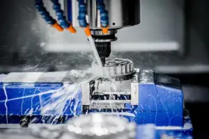
Because of this point-contact relationship, achieving a smooth, accurate final surface on curved-surface parts places much greater demands on tool selection, toolpath density, and step-over control. For surface finishing operations on this category of part, a ball-nose (ball-end) milling cutter is the tool most commonly used. The rounded tip of a ball-end mill is specifically suited to maintaining consistent point contact as it moves across a continuously changing curved surface, allowing it to produce a smoother, more accurate finish on complex three-dimensional geometry than a flat-end or face mill could achieve. This is why, in CNC surface-finishing work, the ball-end mill is treated as something of a default choice whenever the final geometry is a true spatial curve rather than a flat or simply-angled plane.
Summary
Taken as a whole, CNC milling earns its place in a shop's process planning precisely in those situations where conventional milling struggles: mathematically defined and non-circular contours, spatial surfaces with an established mathematical model, dimensionally dense or hard-to-inspect features, hidden internal cavities, tightly toleranced holes and planes, and any incidental simple geometry that can be captured within an existing setup. The four principal part categories - planar-contour, variable-bevel-angle, spatial-curved-surface, and hole-and-thread parts - provide a practical framework for deciding, at the process-planning stage, whether a given feature genuinely calls for CNC milling or could be handled just as effectively by conventional means. Planar parts, being geometrically simpler, generally only require two- or three-axis linkage, while curved-surface parts demand more careful tool selection - typically a ball-end mill - precisely because of the point-contact nature of their machining.