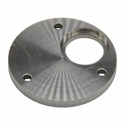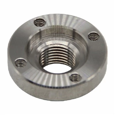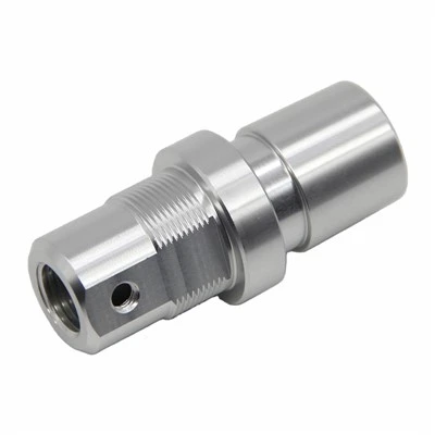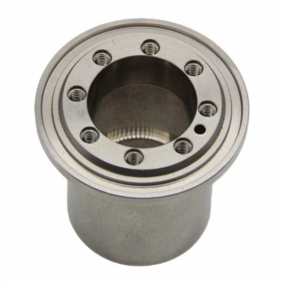

In CNC milling, "processes" and "operation step"are hierarchical, subordinate machining units. A process is the larger machining module, and it contains multiple operations within it. The division between the two should be based primarily on the machining location, the clamping/fixturing method, the cutting tool used, and the cutting parameters. Understanding this hierarchy is essential not only for writing clear process sheets, but also for controlling machining accuracy, minimizing setup time, and building a repeatable workflow that other operators can follow without ambiguity.
Core Methods for Dividing Processes
A process refers to the technological content that is continuously completed on the same CNC milling machine, by the same operator, on the same workpiece, without interruption by a change of machine or operator. In practice, engineers rely on three common approaches to divide processes, and the choice of approach often depends on the geometry of the part, the available fixtures, and the production volume:
1. Division by number of clamping operations : Every time the workpiece is positioned and clamped anew, the machining content completed under that single clamping is treated as one independent process. For example, if the external profile of a workpiece is milled first, and the workpiece must then be re-clamped before the internal cavity can be machined, the external-profile machining and the internal-cavity machining are treated as two separate, independent processes. This division is one of the most fundamental in CNC process planning because re-clamping is the single largest source of positioning error; separating processes at each clamping boundary helps operators and quality inspectors clearly identify where a new datum reference begins, which in turn helps reduce cumulative clamping error and makes it easier to trace the source of any dimensional deviation.
2. Division by machining location : Machining features of the same general type are grouped together into a single process. For instance, all planar (face) milling content across the part can be grouped into one process, while all pocket, cavity, and contour machining content is grouped into a separate process. This approach is especially useful when a part has many repetitive features of the same category scattered across different surfaces, since grouping them together allows the machine to complete similar operations in one continuous run rather than jumping back and forth between different feature types.
3. Division by cutting tool used : Machining content that uses the same category of tool is merged into one process. For example, all the planar-surface content machined with a face mill can be combined into a single process, and all the contour content machined with an end mill can be combined into another. Grouping by tool is a practical strategy because it reduces the number of tool changes required during production. Since every tool change carries not only a time cost but also a repeatability risk (tool length offsets, minor runout differences, and setup variance), minimizing changes by grouping like-tool operations together tends to improve both cycle time and dimensional consistency.
In actual production, these three approaches are rarely used in isolation. Process planners typically combine all three methods - considering clamping constraints, feature grouping, and tool usage together - in order to optimize the overall process division while still guaranteeing the required machining accuracy and improving production efficiency. A well-balanced process plan tries to minimize the number of clamping changes (since each one introduces potential error and consumes setup time), while also minimizing tool changes and keeping machining logically grouped by feature type wherever the geometry allows it.
Core Rules for Dividing Operations
An operation is the further subdivision of a process - the smallest practical unit of machining content. Specifically, an operation refers to the machining content completed within a single process where the machined surface, the cutting tool, and the cutting parameters (spindle speed, feed rate, and depth of cut) all remain unchanged throughout. All three of these conditions must be satisfied simultaneously for the machining content to be considered part of the same operation:
1. A tool change always starts a new operation. Even if the machined surface stays exactly the same, changing the cutting tool means the machining content now belongs to a different operation. For example, within the same process, if a φ10 end mill is first used to rough-mill a pocket, and then a φ5 end mill is used afterward to clean up the corners, this constitutes two separate operations - not one continuous operation with two tools.
2. Adjusting cutting parameters also starts a new operation. Even when the tool and the machined surface remain identical, a change in cutting parameters - such as spindle speed or feed rate - is enough to define a new, separate operation. For example, if the same tool is first used to rough-mill a workpiece at S1200 (spindle speed) and F100 (feed rate), and is then used again to semi-finish-mill the same surface at S1800 and F60, these are treated as two distinct operations, because the process parameters governing the cut have changed even though the tool and surface have not.
3. Special case - the composite operation: On multi-axis CNC milling machines, when multiple tools are used simultaneously to machine different surfaces of the workpiece at the same time, this simultaneous machining can be merged into a single composite operation. For example, if a face mill is machining the top surface at the same time that a side mill is machining a lateral surface, there is no need to split this into sequential, separate operations just because two different tools are involved - because the tools are working concurrently rather than one after another, and there is no interruption or tool-changing step between them.
It is also worth noting that within a single operation, multiple passes are permitted without creating a new operation. For example, if a large amount of material needs to be removed and this requires several successive cutting passes, those multiple passes remain part of the same operation as long as the surface, tool, and cutting parameters are unchanged - there is no need to artificially split out a new operation just because the cut was executed in more than one pass.
A Worked Example: Process and Operation Breakdown for a Typical Part
To make this hierarchy concrete, consider the machining of an aluminum alloy square cover plate as an example:
Process 1: First clamping, workpiece oriented with the bottom face down, machined with a φ20 face mill
Operation 1: Rough-mill the top surface at S1200, F100 (executed across 3 passes to remove the bulk of the stock material)
Operation 2: Semi-finish-mill the top surface at S1800, F60 to bring it to the required dimensional tolerance
Operation 3: Mill the counterbore recesses for the bolt holes on the top surface at S1800, F60
Process 2: Workpiece flipped and re-clamped, machined with a φ10 end mill
Operation 1: Rough-mill the side walls of the grooves around the perimeter of the cover plate at S1500, F80
Operation 2: Finish-mill the groove side walls to final dimension at S2000, F50
Process 3: Tool changed to a φ3 drill to machine the locating (dowel) holes. This is treated as an independent process. However, if the milling machine has integrated drilling capability and the drilling can be completed under the same clamping setup as an existing process, it can instead be merged into the corresponding process rather than being listed as a separate one.
This example illustrates how the three process-division methods discussed above interact in practice: Process 1 and Process 2 are separated primarily because of a clamping change (the workpiece is physically flipped and re-fixtured), while the operations within each process are separated because of changes in tool and/or cutting parameters. Process 3, meanwhile, shows how the boundary between "process" and "operation" is not always rigid - it depends on the specific capability of the machine tool and whether the additional machining content can realistically be completed without breaking the current clamping setup.
Safety Reminder
Throughout this entire workflow - during clamping, re-clamping, and every tool change - operators must strictly follow the CNC milling machine's safety operating procedures. In particular, the power supply must be cut off before performing any clamping or tool-change operation, in order to prevent accidental machine movement and avoid safety incidents. Adhering to this discipline is just as important to a sound process plan as the technical logic of dividing processes and operations correctly.