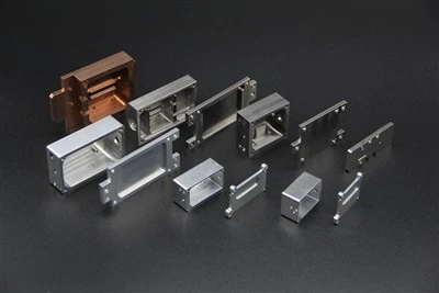
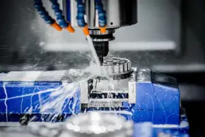
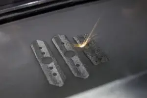

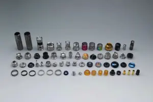

Precision standards for milling operations vary depending on equipment type and machining conditions. Standard milling equipment can achieve dimensional accuracy of 0.01mm, while traditional milling lathes (such as the CA6140A) typically leave the factory with an accuracy of 0.02mm. The following analysis covers three areas: equipment type, vibration effects, and precision calibration.
Equipment Type and Precision Differences
Precision of new equipment: Modern milling equipment, through optimized process-system rigidity (machine power, fixture design, tool structure), can hold dimensional accuracy within 0.01mm - suitable for high-precision component machining. This level of performance typically depends on several converging factors: high-rigidity spindle bearings, precision-ground linear guideways with minimal backlash, thermally stable structural castings, and closed-loop feedback control systems that continuously compensate for positioning error. Investment in such equipment is generally justified when producing parts with tight tolerances, complex geometries, or when machining difficult-to-cut materials where any additional vibration or deflection would compromise surface finish.
Precision of traditional equipment: Standard milling lathes represented by the CA6140A, constrained by clearances in the spindle, guideways, and transmission mechanisms, typically leave the factory with an accuracy of 0.02mm and require regular maintenance and adjustment to sustain performance. It's worth noting that this factory-rated accuracy represents a best-case baseline - as the machine accumulates operating hours, wear in the leadscrew, guideway surfaces, and bearing seats can gradually widen these clearances, causing actual working accuracy to drift further from the nominal 0.02mm figure unless addressed through the maintenance and calibration practices discussed below. For workshops relying primarily on this class of equipment, building a preventive maintenance schedule - rather than only reacting to visible accuracy problems - is often the more cost-effective long-term approach.
Vibration's Impact on Precision
Milling vibration is a primary factor affecting precision, arising from the following causes:
Cutting force fluctuation: The intermittent, multi-edge cutting action of milling cutters causes cyclical variation in cutting force, triggering vibration throughout the process system. This periodic loading and unloading of the cutting edges is inherent to the milling process itself (unlike turning, which involves continuous engagement), which is part of why milling operations are generally more prone to vibration-related accuracy issues than single-point turning operations of comparable rigidity.
Up-milling (conventional milling) slippage: During up-milling, the cutter engaging the workpiece surface produces slippage, causing the tool shank to lift and then drop - forming periodic vibration. This phenomenon is one of the key reasons many shops prefer climb milling (down-milling) for finishing passes where surface quality is critical, since the chip thickness in climb milling starts thick and tapers to zero, generally producing a smoother cutting action - though climb milling brings its own considerations around backlash and workpiece pull-in that must be managed.
System clearance: Clearances present in the machine's spindle, guideways, and transmission mechanisms intensify vibration. Even clearances on the order of a few microns, when combined with the cyclical loading from intermittent cutting, can amplify into perceptible chatter marks on the finished surface - which is why clearance inspection is treated as a distinct calibration step rather than folded into general maintenance.
Insufficient rigidity: Inadequate rigidity in the fixture, tool shank, or workpiece leads to deformation or vibration during machining. This is particularly pronounced with thin-walled or slender workpieces, where the workpiece itself - not just the machine - becomes the weak link in the system's overall stiffness, sometimes requiring auxiliary supports or a redesigned clamping strategy independent of any machine-side improvements.
Control Measures:
Enhance rigidity: Select high-power machines and rigid fixtures, and optimize tool structural dimensions (e.g., shortening the tool shank, reducing diameter). As a general principle, tool overhang should be kept as short as practically possible for the given operation, since deflection increases with the cube of overhang length - even a modest reduction in shank length can yield a disproportionate improvement in stability.
Adjust clearances: Before milling, inspect and adjust clearances at all machine locations, and lock unused feed directions during machining. This last point is frequently overlooked in practice - leaving an idle axis unlocked allows it to act as an additional degree of freedom for vibration to propagate through, even when that axis isn't actively being driven.
Optimize parameters: Reasonably select cutting angles and milling parameters (such as feed rate and depth of cut) to reduce sources of vibration. When chatter does appear despite otherwise sound setup, adjusting spindle speed to shift the cutting frequency away from the system's natural resonance frequency can often resolve the issue faster than reducing feed or depth alone - a technique sometimes referred to as working within the machine's "stability lobes."
Precision Calibration Methods
To ensure milling operations consistently and reliably meet precision standards over the long term, the following calibrations should be performed regularly:
X-axis correction: Loosen the 4 mounting bolts (retaining some frictional resistance), adjust the worktable's left-right angle by rotating the adjustment bolts, and measure the spindle face position with a dial indicator. Retaining partial friction during this adjustment is important - fully loosening the bolts can allow the table to shift unpredictably under its own weight or under the light pressure of the indicator probe, undermining the accuracy of the reading being taken.
Y-axis correction: Loosen 3 bolts (avoid over-loosening), use the arm's rotation bolts to fine-tune the worktable's front-back position, again measuring the spindle face with a dial indicator. As with the X-axis procedure, this adjustment is typically iterative - small corrections followed by re-measurement - rather than a single-pass adjustment, since the table's response to bolt rotation is not perfectly linear near the correct position.
Level correction: Place a spirit level on the worktable surface, check the levelness at points A and B, with an allowable deviation of 0.06mm/m; if necessary, install shims beneath the machine to make adjustments. Level correction is generally treated as a prerequisite check before the X- and Y-axis procedures above, since a machine bed that is not level to begin with can introduce systematic errors that make subsequent axis calibration difficult to interpret correctly.
Beyond these three core procedures, many shops also incorporate a periodic spindle runout check using a dial indicator against a test bar, since spindle runout - even when the guideways and worktable are properly calibrated - can independently degrade both dimensional accuracy and surface finish. The recommended calibration interval varies by usage intensity and shop environment, but as a general guideline, machines in continuous production use benefit from more frequent verification than those used intermittently, and any machine that has recently experienced a collision, overload, or significant temperature swing should be re-checked regardless of the normal schedule.
Summary
Precision standards in milling are influenced by three factors: equipment type, vibration control, and calibration maintenance. New equipment can achieve 0.01mm, while traditional equipment achieves 0.02mm; through optimizing process-system rigidity, reducing sources of vibration, and performing regular calibration, machining precision can be further improved and maintained. In practical application, the appropriate precision-control strategy should be selected based on the specific equipment conditions and machining requirements at hand. Ultimately, no single measure - whether upgrading equipment, tightening clearances, or following a calibration schedule - is sufficient on its own; sustained precision is the product of treating equipment selection, vibration management, and calibration discipline as an integrated system rather than addressing each in isolation.