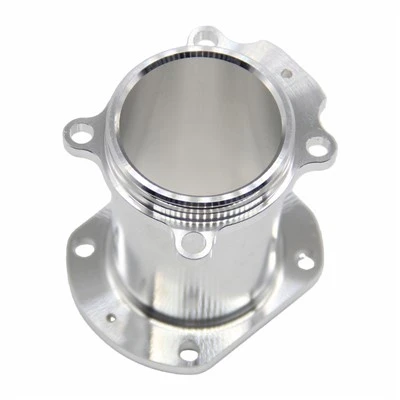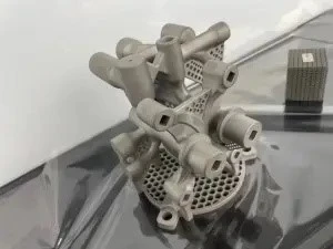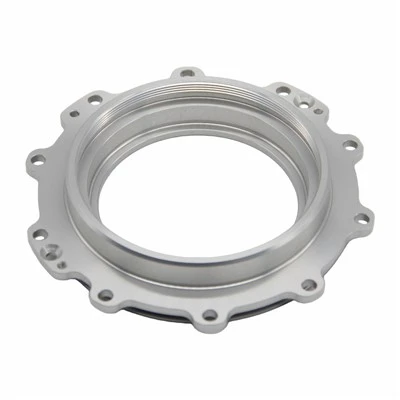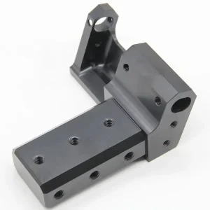
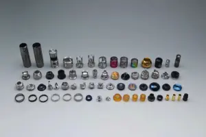

5-axis CNC machining is a high-precision cutting process that simultaneously controls three linear axes (X/Y/Z) together with two rotary axes (most commonly A/B or A/C axes), allowing the cutting tool or the workpiece to be oriented into virtually any spatial position. Because the tool can approach a surface from almost any angle, a single setup is often enough to complete every operation a complex-surface part requires. This is the core advantage of the technology: it removes the need to unclamp and re-fixture the part between operations, which in turn eliminates the positioning errors that accumulate every time a workpiece is moved, and it delivers a meaningful boost in both machining efficiency and surface quality compared with 3-axis or even 4-axis processes.
Basic Structural Classification of 5-Axis Machine Tools
Layout Types
5-axis machines are generally grouped into three structural layouts, each suited to a different scale and style of work:
Cradle-type (trunnion) structure: Both rotary axes are integrated into the worktable, typically in an A/C-axis configuration. This layout offers excellent rigidity and is well suited to small and medium-sized precision parts, where tight tolerances and a compact working envelope matter more than raw table size.
Swivel-head (rotary-head) structure: Both rotary axes are built into the spindle head, commonly in a B/C-axis arrangement, while the worktable itself stays fixed. Because the table doesn't move or tilt, this configuration is the natural choice for large workpieces that would be impractical to swing on a rotating table.
Hybrid structure: One rotary axis sits on the worktable and the other on the spindle head. This split arrangement balances machining rigidity against orientation flexibility, giving shops a middle path when neither a pure cradle-type nor a pure swivel-head machine fits the job perfectly.
Core Functional Components
Behind every 5-axis machine's ability to hold tight tolerances is a set of core components working together:
5-axis simultaneous CNC control system: Mainstream controllers currently in wide use include Siemens 840Dsl, Heidenhain TNC640, and Fanuc 31i-B5, all of which must support 5-axis interpolation and the coordinate transformation functions (such as RTCP/TCPC) that keep the tool tip on the programmed path as the rotary axes move.
High-precision rotary-axis feedback devices: These typically use linear or rotary glass-scale encoders, which keep rotary-axis positioning accuracy within ±5 arcseconds and repeatability within ±3 arcseconds - a level of feedback precision that is essential once a fifth axis is added to the error chain.
High-rigidity spindle units: Paired with water- or oil-cooling systems, spindle speeds commonly range from 8,000 to 30,000 r/min, which lets the machine adapt to the very different cutting demands of aluminum, steel, titanium, and other engineering materials.
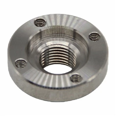
Core Process Workflow
Pre-Machining Preparation
Before any chips fly, two preparation stages set the foundation for a successful job:
Workpiece fixturing: Depending on the size and shape of the part, shops choose between vises, vacuum chucks, or dedicated fixtures, always with the goal of maximizing clamping rigidity and locating accuracy to minimize fixturing-induced error - a step that matters even more in 5-axis work, since the tool may approach the part from angles that put unusual loads on the fixture.
Programming and simulation: Toolpaths are generated in 5-axis CAM software such as UG NX, Mastercam, or Cimatron, and then verified in virtual simulation software like VERICUT to catch interference and collision risks before the program ever touches the machine. Given how many degrees of freedom a 5-axis toolpath has to account for, this simulation stage is not optional - it's the main line of defense against a crashed spindle or a scrapped fixture.
Machining Execution
Machining then proceeds through three progressively finer stages:
Roughing: Carbide end mills or corn-cob (roughing) mills are the usual choice, run with an aggressive, large-stock-removal strategy to clear material quickly and get the part close to its final shape.
Semi-finishing: The tool's cutting orientation is adjusted to clean out the residual stock left behind corners and fillets by the roughing pass, preparing a consistent, predictable stock allowance for the finishing stage.
Finishing: Ball-nose or bull-nose end mills take over, with cutting speed and feed rate tightly controlled to hold surface roughness at Ra ≤ 1.6 μm - the kind of finish that matters most on the free-form surfaces 5-axis machining is chosen for in the first place.
Post-Machining Inspection
Once machining is complete, a coordinate measuring machine (CMM) checks the part's dimensions and geometric tolerances, and the results feed back into the process to correct parameters for subsequent runs - turning inspection into a continuous improvement loop rather than a one-time pass/fail check.
Typical Application Scenarios
5-axis machining earns its premium in industries where geometry, tolerance, or both leave no room for compromise:
Aerospace: Integrally bladed disks (blisks), aero-engine blades, and satellite structural components all demand high-precision machining of complex surfaces, with tolerance requirements that can reach the micron level.
Mold and die manufacturing: Automotive body panel dies and medical device injection molds with irregular contoured surfaces can often be finished in a single setup covering multiple faces, saving both time and setup-related error.
Precision hardware: Drone airframes with unconventional geometry, high-end bicycle frames, and bathroom hardware fittings are all produced at volume with 5-axis precision.
Medical devices: Artificial joints, orthopedic implants, and other personalized, patient-specific parts rely on 5-axis machining to hit the tight, individualized tolerances that off-the-shelf implants can't match.
Key Process Control Parameters
Holding accuracy and surface quality on a 5-axis machine comes down to a handful of parameters that operators watch closely:
Rotary-axis feed rate: Typically kept between 300 and 800 mm/min, to avoid the vibration and precision loss that high-speed rotary motion can introduce.
Cutting-parameter matching: Parameters are adjusted by material. For aluminum alloy finishing, cutting speed runs 150–250 m/min; for titanium alloy, 30–60 m/min; feed rate is generally 0.1–0.2 mm/r for roughing and 0.05–0.1 mm/r for finishing.
Safety clearance: A minimum 2 mm collision-check margin is maintained between the toolpath and any fixture or workpiece surface, to prevent spindle collisions during machining.
Error compensation: Rotary-axis backlash and positioning errors are calibrated on a regular schedule, with compensation parameters set in the CNC system to keep accuracy from drifting over time.
Safety Operating Boundaries
Because 5-axis machines combine high spindle speeds with moving rotary axes, safety protocol is built into every stage of operation:
Before startup, check the rotary-axis limit switches and lubrication system pressure, and confirm everything is normal before powering on the machine.
A dry-run verification is mandatory before actual machining begins, to confirm the toolpath carries no collision risk.
During machining, the machine's guard doors must never be opened, and personnel are prohibited from entering the safety zone while the rotary axes are in motion.
When changing fixtures or tools, the machine's main power must be cut and an "Under Maintenance" warning sign hung in place.
Rotary-axis positioning accuracy should be inspected and recalibrated at least once every six months, as part of a regular 5-axis precision verification program.
Taken together, these structural, procedural, and safety elements are what let 5-axis machining deliver on its central promise: complex, multi-face parts machined to tight tolerance in a single setup, with far less accumulated error and far more consistent surface quality than traditional multi-setup processes can achieve.